Diamagnetic Lateral Force Calibrator (D-LFC)
Lateral force calibration of AFM (LFM, FFM)

|
Diamagnetic Lateral Force Calibrator (D-LFC)Lateral force calibration of AFM (LFM, FFM) |
|
|
|
||
Introduction |
We noticed that most AFM thin film cantilevers have typical lateral spring constants on the order of 100 nN/nm and an operational range within 100 nm of deflection. A compliant load cell with a spring constant of ~ 100 pN/nm can accurately calibrate the AFM force constants. To apply a small known force on the cantilever-tip assembly, the load cell should stay "freely" in air without touching any other neighboring components (otherwise it will introduce extra non-controllable adhesion and friction forces). It sounds like a fantasy at the first thinking, but diamagnetism makes all these happened. In the following sections, you will learn how to make this magic load cell, i.e. D-LFC, in a few easy steps.
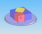
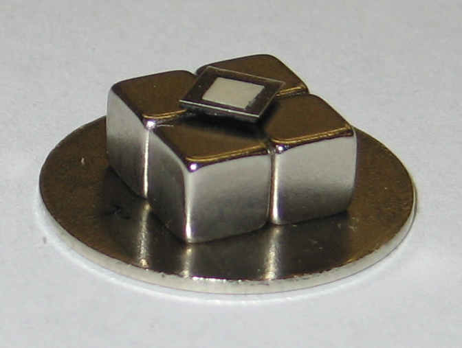
Figure 3. A schematic and a picture of a D-LFC
Determination of D-LFC Spring Constant |
| Material |  |
| Water | -8.8 |
| Gold | -34 |
| Bismuth | -170 |
| Graphite rod | -160 |
Pyrolytic graphite  |
-450 |
| Pyrolytic graphite = | -85 |
Table 1. Values of susceptibility for various diamagnetic materials (in SI units)
Among these materials, graphite and bismuth display very strong diamagnetism. The susceptibility of a CVD-grown pyrolytic graphite (PG) is highly anisotropic and the susceptibility in the direction perpendicular to the basal plane is several times higher than that in the direction parallel to the plane. This strong anisotropy is useful to suspend a PG sheet in a magnetic field, balancing the gravity force, while the lateral spring constant of levitation is tuned to be small.
You may notice that there are two key points for a successful levitation: right materials and right setup
The levitated mass is made of pyrolytic graphite (PG) due to the above reasons. I would like to mention that a regular cheap PG sheet is good enough for the levitation purpose, you don't need the expensive highly order pyrolytic graphite (HOPG). And of course you also need some strong magnets. I recommend you to choose Neodymium-iron-boron (NdFeB) permanent magnets, usually they are very handy and come with much higher grades than other types. There are many vendors selling these rare-earth magnets with all kinds of shapes and grades; some of them even have a kit for only a few bucks including both pyrolytic graphite sheets and magnets. Here are some links for you :)
http://www.rare-earth-magnets.com
Here comes the first step of our DIY, I will show you how to set them up in a moment.
Step-1: Buy some pyrolytic graphite sheets and magnets for yourself, choose the appropriate size and grade for your application.
To make the PG sheet sit still above the magnets, we need apply to the magnetic forces in a stable way. There are many tricks you can do, an easy way is to use the four- magnet setup.
Step-2: Use four magnets and align their poles vertically and alternate such that two with north facing up and two with south facing up, diagonally.
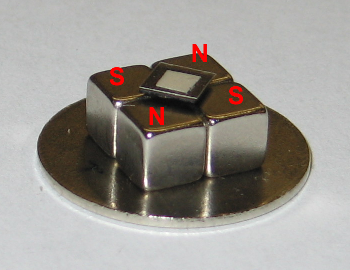
Figure 4. Four-magnet setup for D-LFC
Some useful tips for you:
Once you have the magnet array is ready, we can move to the next step to prepare the floating graphite sheet.
Step-3: Cut the pyrolytic graphite into square-shaped sheets with proper thickness and modify the top surface so that it's flat enough to be used in AFM.
The pyrolytic graphite has a layered structure and is readily to be cleaved. A razor blade or a sharp knife works very nicely for this job.
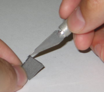
Figure 5. Cutting a pyrolytic graphite sheet with an X-ACTO knife
This is a very important step because the shape and size of the PG sheet largely determine the spring constant of your D-LFC system. The spring constant also depends on the quality of your PG sheet and the grade of the magnets. You need to try and figure out the right dimensions for your own application. I would only provide some guild lines here based on our experiences and finite element calculation:
Because the surface of the pyrolytic graphite sheet is usually very rough, the top surface should be modified to avoid contaminating and damaging your AFM probes. It is well known that mica can be easily cleaved to offer an atomically flat surface; Gluing a thin mica sheet on top of the pyrolytic graphite sheet is not a bad choice.
After following all the steps above, your D-LFC should almost be ready now. You can play with it by pushing the PG sheet a bit off the center: the PG sheet will vibrate harmonically in air like a standard spring-mass system (video here). We may notice that the vibration amplitude decays slowly, this is due to the damping effects of the air drag and eddy current.
To use this D-LFC to calibrate the lateral force constants, it is necessary to know the spring constants of the D-LFC itself. How can we do that?
We know that the motion could be described by the equation of free vibration (for details please see the paper)
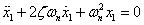 (3)
(3)
By measuring the mass, vibration frequency and amplitude decaying rate, we can calculate the spring constant conveniently. So the next step is to
Step-4: Monitor the free vibration of the PG sheet in air then calculate the spring costant of D-LFC
Ideally we should monitor the PG sheet position vs. time for the vibration process. There are many ways you can think of, e.g. video recording or a laser Doppler velocimeter. In our case, we use a simple setup called laser displacement tracer. The basic idea is that a sheet of a 10 mW He-Ne laser light was partially blocked by the edge of the vibrating PG. The transmitted light intensity was detected by a photodiode. Please let me know if you have easier or better ideas :)
A typical time trace of the amplitude using our displacement tracer is shown below :
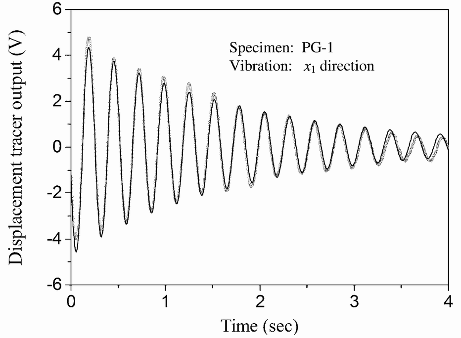
Figure 5. Time trace of the free vibration amplitude
The amplitude curve is fitted using the form of the general solution to the equation (3)
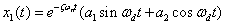 (4)
(4)
where 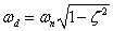 .
.
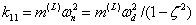
Once you have the values for  and
and  , the spring constant of D-LFC can be calculated as
 (5)
(5)
where  is the mass of the PG composite sheet.
If the damping is small, which is true for most of the cases, and  are approximately the same. So in stead of curve fitting, you can
simply measure the vibration frequency and use it to calculate the
spring constants.
are approximately the same. So in stead of curve fitting, you can
simply measure the vibration frequency and use it to calculate the
spring constants.
Congratulations! Your D-LFC is now ready to go :)
In the next section, you will learn how to use this magic device to calibrate your AFM system.